Hitachi ZW30, ZW40, ZW50 Wheel Loader Service Repair Manual
The manual is applicable for the Hitachi ZW30, ZW40, ZW50 Wheel Loader Model
Format: PDF
Language: English
Service Manual consists of the following:
For Model ZW30, ZW40, ZW50 as mentioned above:
Service Manual (Troubleshooting) : Vol. No.T4EK-E
Workshop Manual : Vol. No.W4EK-E
Table of Content of the Workshop Manual
SECTION 1 GENERAL
Group 1 Precautions for Disassembling
and Assembling
Group 2 Tightening
Group 3 Painting
SECTION 2 BODY
Group 1 Canopy
Group 2 Cab
Group 3 Counterweight
Group 4 Center Hinge
Group 5 Engine Hood
Group 6 HST Pump and Main Pump
Group 7 HST Motor
Group 8 Control Valve
SECTION 3 TRAVEL SYSTEM
Group 1 Tire
Group 2 Reduction Gear
Group 3 Axle
Group 4 Propeller Shaft
Group 5 Master Cylinder
Group 6 Parking Brake Solenoid
Group 7 Inching Valve
Group 8 Power Steering
Group 9 Steering Cylinder
SECTION 4 FRONT ATTACHMENT
Group 1 Front Attachment
Group 2 Cylinder
Table of Content of the Technical Manual
SECTION 1 GENERAL
Group 1 Specification
Group 2 Component Specification
Group 3 Component Layout
SECTION 2 SYSTEM
Group 1 Fuel System
Group 2 Hydraulic System
Group 3 Electrical System
SECTION 3 COMPONENT OPERATION
Group 1 HST Pump
Group 2 HST Motor
Group 3 Axle
Group 4 Brake
Group 5 Orbitrol
Group 6 Loading Control Valve
Group 7 Main Pump
SECTION 4 OPERATIONAL PERFORMANCE
TEST
Group 1 Introduction
Group 2 Standard
Group 3 Engine Test
Group 4 Wheel Loader Test
SECTION 5 TROUBLESHOOTING
Group 1 Diagnosing Procedure
Group 2 Failure List
Group 3 Engine
Group 4 Vehicle Performance
Group 5 Air Conditioner
Hitachi ZW30, ZW40, ZW50 Wheel Loader Service Repair Manual
Manual guide composition
Hitachi ZAXIS ZW30, ZW40, ZW50 service manual consists of the Technical and the Workshop Manual.
- Information included in the Service Manual: Technical information needed for redelivery and delivery, operation and activation of all devices and systems, operational performance tests, and troubleshooting procedures.
- Information included in the Workshop Manual: Technical information needed for maintenance and repair of the machine, tools and devices needed for maintenance and repair, maintenance standards, and removal / installation and assemble / disassemble procedures.
Travel System and Master Cylinder

Procedures
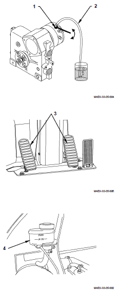
1. Insert transparent vinyl tube (2) to bleeder screw (1).
Put the other one end into the clean container so that brake oil does not spray out.
2. Depress the brake pedal (3) several times.
Loosen bleeder screw (1) from half turn to one turn with the pedal depressed.
Drain brake oil and trapped air.
3. Tighten bleeder screw (1).
Release brake pedal (3).
4. Repeat step 2 and step 3 until clean brake oil flows in vinyl hose (2) and bubbles disappear completely.
5. When bubbles completely disappear in the hose, tighten bleeder screw (1) with brake pedal (3) depressed.
6. After bleeding air, adjust the brake oil level in brake oil tank (4).
When the brake oil level is within MIN to MAX, the amount of brake oil is proper.


Reviews
There are no reviews yet.